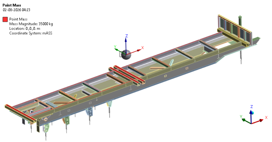
FEA Simulation — Mass Condition
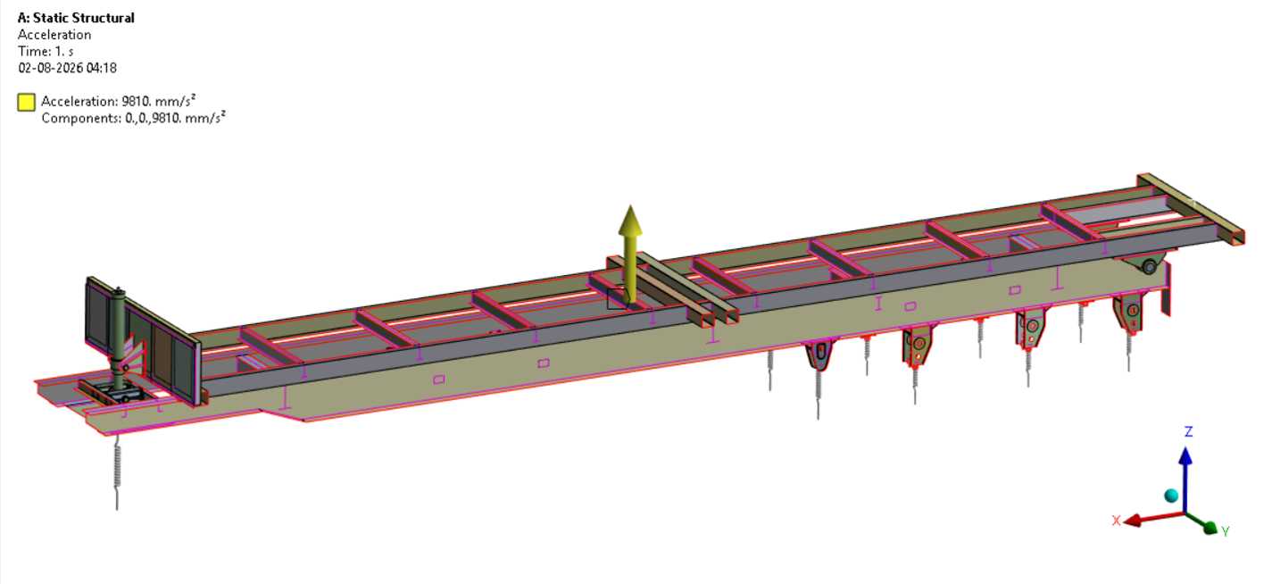
FEA Simulation — Loading Condition
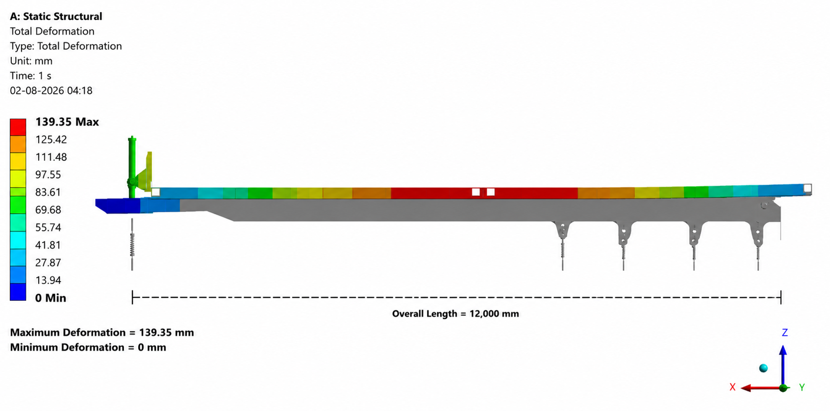
FEA Simulation — Total Deformation
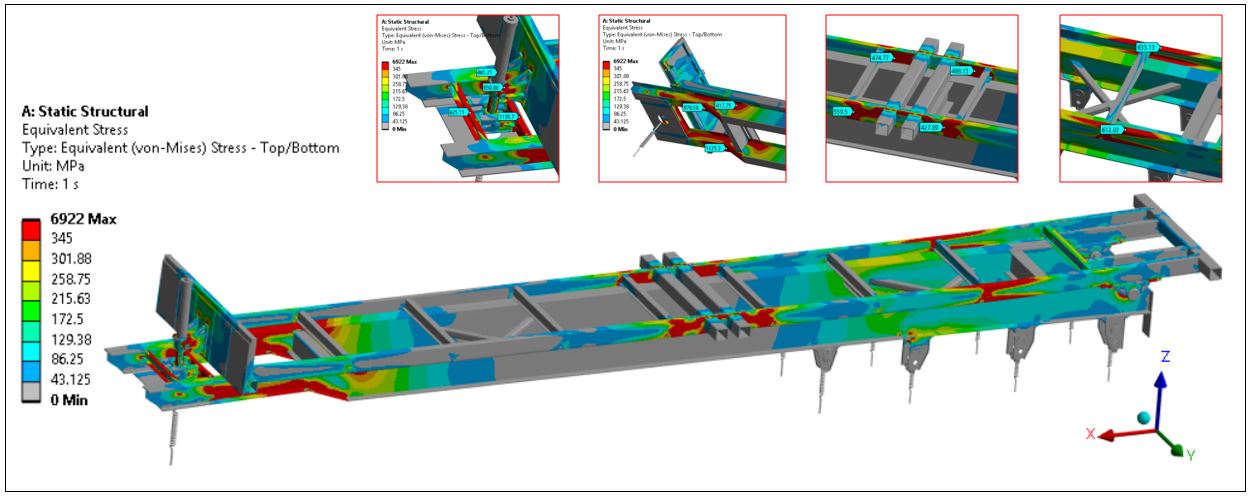
FEA Simulation — Stress Analysis
Material Properties & Loading Parameters
| Parameter | Value | Unit |
|---|---|---|
| Material | ASTM A572 Grade 50 Steel | |
| Density | 7850 | kg/m³ |
| Young's Modulus | 200 | GPa |
| Poisson's Ratio | 0.30 | — |
| Yield Strength | 345 | MPa |
| Ultimate Tensile Strength | 450–620 | MPa |
| Applied Load | 35-Ton Payload + Self-weight (1 g) | |
| Front Axle Spring Stiffness | 330 (each side) | N/mm |
| Rear Axle Spring Stiffness | 440 (each side, per axle) | N/mm |
| Coefficient of Friction (Frame Contact) | 0.20 | — |
| Weld Representation | 6 mm fillet weld (leg size) | — |
Executive Summary
This case study presents a static structural Finite Element Analysis (FEA) of the chassis–body subframe assembly of a 35-ton tipper truck. The chassis and body subframe were modelled using shell elements, with the suspension and tyre system represented through equivalent spring supports at the axle mounting locations (Front: 330 N/mm, Rear: 440 N/mm per axle).
The assembly was analysed under a combined static loading condition consisting of the self-weight (1 g) of the complete structure and a 35-ton payload (343.35 kN) applied at the centre of gravity of the loaded tipper body through a Remote Point scoped to the body subframe cross-members. The analysis was carried out for Insight Design Consultant, with structural analysis performed by Santanu and Team and drawings prepared by Sumit Gorai.
Study Objectives
The FEA study was conducted with the following primary objectives:
FEA Simulation Observations
Predictable Deformation Pattern
The maximum total deformation of 139.35 mm occurs at the unsupported free end of the body subframe, while the minimum deformation is observed at the spring-supported mounting locations. Deformation increases gradually from the supported regions toward the free end, confirming proper load transfer through the chassis and body subframe.
Effective Suspension Support Response
The equivalent spring supports (Front: 330 N/mm, Rear: 440 N/mm per axle) effectively resist vertical deflection at the mounting locations, demonstrating stable structural behaviour of the chassis under the applied 35-ton static loading.
Yield Strength Exceeded at Critical Regions
The maximum equivalent von-Mises stress exceeds the material yield limit of 345 MPa, indicating localized material yielding under the applied load. This finding is the primary structural concern raised by the analysis.
Localized Stress Concentration at Load Transfer Regions
The maximum von-Mises stress is concentrated at the hydraulic cylinder mounting and body subframe connection regions due to localized load transfer, while the longitudinal chassis rails exhibit a well-distributed stress pattern under the 35-ton static payload.
Boundary Conditions & Equivalent Spring Supports

Stress & Deformation Profile by Region
The FEA results reveal distinct structural response zones across the chassis–body subframe assembly, ranging from well-supported low-deformation regions to critical stress concentration zones at load transfer points.
Performance Evaluation Matrix
Final Assessment Summary
The table below summarizes the key findings and final structural assessment of the chassis–body subframe assembly:
| Parameter | Result |
|---|---|
| Applied Load | 35-ton Payload + Self-weight (1 g) |
| Material | ASTM A572 Grade 50 (Yield Strength = 345 MPa) |
| Boundary Condition | Equivalent Spring Supports (Front: 330 N/mm, Rear: 440 N/mm per axle) |
| Max Total Deformation | 139.35 mm |
| Von-Mises Stress | Exceeds material yield strength in localized regions |
| Critical Region | Hydraulic cylinder mounting bracket, body subframe mounting brackets, front chassis connection |
| Margin of Safety (MoS) | −0.73 |
| Design Status | Requires reinforcement and optimization before final implementation |
Engineering Recommendations
Local Reinforcement at Hydraulic Cylinder Mounting
Introduce additional gusset plates or increased plate thickness at the hydraulic cylinder mounting bracket to reduce the localized stress concentration below the material yield limit.
- Add reinforcing gussets between the mounting bracket and main chassis rail
- Review weld leg size and fillet geometry at this connection
- Re-run FEA after reinforcement to confirm stress reduction below 345 MPa
Body Subframe Connection Strengthening
Redesign the body subframe mounting bracket geometry to reduce geometric discontinuities that concentrate stress at the auxiliary-to-main-frame connection.
- Increase bracket fillet radius to reduce stress concentration factor
- Verify bonded/welded connection capacity against the revised load path
- Consider local doubler plates at the connection interface
Front Chassis Connection Review
Evaluate the front chassis connection region identified as a critical zone, and consider load path redistribution to reduce peak stress at this location.
- Verify weld quality and inspection records at the front connection
- Consider tapered stiffener plates along the load transfer path
Design Verification After Reinforcement
Following implementation of the recommended reinforcements, a repeat static structural FEA is recommended to confirm:
- Von-Mises stress remains below the 345 MPa yield limit at all critical regions
- Margin of Safety (MoS) is positive across the assembly
- Total deformation remains within acceptable serviceability limits
Conclusion
The static structural FEA of the 35-ton tipper truck chassis–body subframe assembly, conducted under a combined self-weight (1 g) and 35-ton payload loading condition, indicates that the maximum deformation of 139.35 mm occurs at the unsupported free end of the body subframe due to bending, while the spring-supported mounting locations show minimal deformation, confirming effective support from the equivalent suspension system.
However, the equivalent von-Mises stress exceeds the material yield strength of 345 MPa (ASTM A572 Grade 50) in localized regions, concentrated at the hydraulic cylinder mounting and body subframe connection points, resulting in a negative Margin of Safety of −0.73. The overall performance rating of 5.5 / 10 indicates that the current design requires reinforcement and optimization in the identified critical regions before final implementation.